【1】What Are SI / PI / EMI?
First, let’s sort out the three terms.
① SI (Signal Integrity)
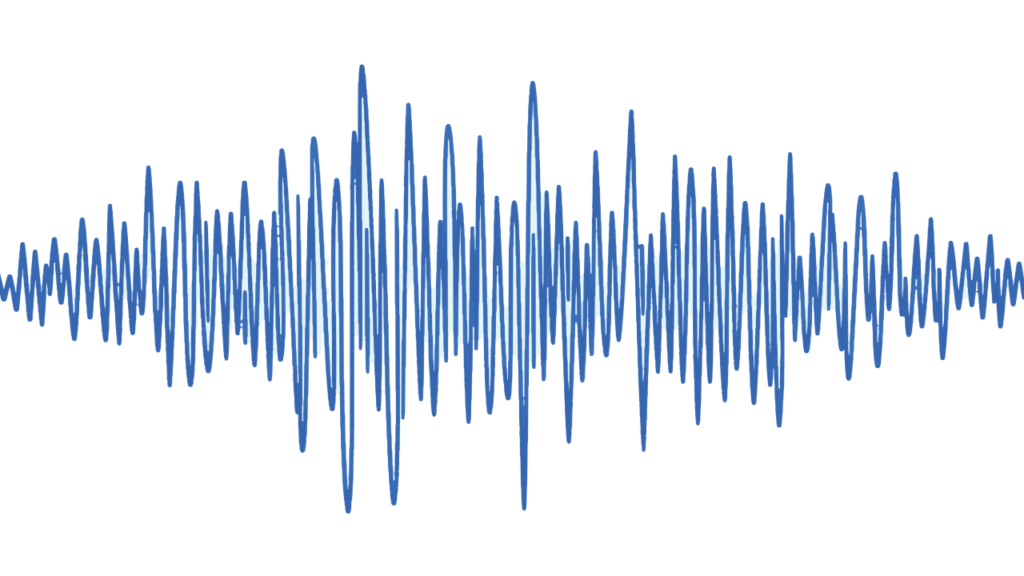
The field that deals with whether signals arrive with the correct shape, correct timing, and correct voltage.
Example problems:
・Slower rise times
・Ringing
・Jitter
・Crosstalk
Most important for high-speed I/O (PCIe, DDR, SerDes).
② PI (Power Integrity)
Deals with whether the power supply can deliver sufficient current stably and instantaneously.
Example problems:
・Supply voltage drop
・Simultaneous switching noise (SSN)
・Ground bounce
Fatal for AI chips and HBM.
③ EMI (Electromagnetic Interference)
Problems in which unwanted electromagnetic waves:
・Adversely affect other circuits
・Violate standards (FCC / CISPR, etc.)
It tends to become the final hurdle that can stop a product from shipping.
【2】Why the Problems Become More Serious in Advanced Packages
The reasons are as follows.
① Signal speeds are extremely fast
At tens of Gbps to around 100 Gbps, wiring is no longer a simple conductor but a transmission line.
② Wiring density is extraordinarily high
In fan-out, 2.5D, and 3D, the distance to adjacent wiring becomes extremely short, and crosstalk increases sharply.
③ Currents are too large
In AI chips, instantaneous currents on the order of hundreds of amperes flow.
If the power network is unstable, problems arise immediately.
【3】Typical SI (Signal Integrity) Challenges
Impedance Mismatch
・Variations in wiring width, thickness, and dielectric constant
・RDL design errors
→ Reflections and ringing occur.
Crosstalk
・Electromagnetic coupling from adjacent wiring
・Especially pronounced in high-speed differential signals
Countermeasures:
・Wider wiring spacing
・Placement of GND shields
・Optimized layer stack-up
Jitter and Insufficient Timing Margin
・Variations in wiring delay
・Temperature and voltage fluctuations
The more scaling advances, the more design margin disappears.
【4】Typical PI (Power Integrity) Challenges
Voltage Drop (IR Drop)
・Increased current × wiring resistance
・Power wiring inside the package becomes the bottleneck
Simultaneous Switching Noise (SSN)
・Many transistors switch ON/OFF at the same time
・Power and GND fluctuate
Countermeasures
・Optimal placement of decoupling capacitors
・Strengthening power and GND planes
・Backside power delivery (BSPD)
・Co-design of the package and chip
【5】EMI (Electromagnetic Interference) Challenges and Countermeasures
Situations Where EMI Becomes a Problem
・Wireless devices (5G, Wi-Fi)
・Automotive (ADAS)
・Medical devices
・High-speed I/O products
Main Countermeasures
・GND shield structures
・Metal caps and shield cans
・Physical separation of noise sources and antennas
・Minimizing wiring loop area
・Adding filters and chokes
Leaving EMI countermeasures until the end is a nightmare → the golden rule is to build them in from the initial design.
【6】SI / PI / EMI Perspectives by Advanced Package Type
Fan-out
・RDL tends to become long → SI deteriorates
・Power wiring is thin → PI is a challenge
Countermeasures:
・Optimizing RDL width and thickness
・Adding dedicated power RDL layers
2.5D / Chiplet
・Chip-to-chip interfaces are ultra-high-speed
・PI design for HBM is the most difficult
Countermeasures:
・Short wiring
・Wideband decoupling
・Dedicated structures such as CoWoS
3D-IC
・TSVs affect both SI and PI
・Heat and power supply noise are linked
Countermeasures:
・Optimizing TSV placement
・Dedicated power TSVs
・Simultaneous optimization of heat, power, and signals
【7】Latest Trends
・Simultaneous simulation of SI/PI/EMI
・Full co-design of chip + package + substrate
・AI-based optimization of wiring and placement
・Full-scale introduction of backside power delivery
・Evolution of high-frequency materials (low Dk / low Df)
【8】Summary
・With higher speeds and densities, SI/PI/EMI cannot be avoided
・Signals, power, and electromagnetics affect one another
・Building them in from the initial design is essential
・Challenges differ for fan-out, 2.5D, and 3D
・Co-design and simulation determine competitiveness
Comprehension Check
1.Explain the difference between SI and PI in one sentence.
2.Why must wiring be treated as a transmission line for high-speed signals?
3.Why should EMI countermeasures be implemented from the early stages of design?
Column Supervisor: Koji Kakumoto (President, OTIS Co., Ltd.)
After studying abroad and working in planning and development at a trading company, he joined OTIS Co., Ltd. in 2011. While primarily working in the Corporate Planning Department, he has also served concurrently in manufacturing and technical divisions, and since 2018 has served as President, working to drive business growth and strengthen the organization.
This article is a general technical explanation intended for educational purposes and does not refer to any specific company, product, or technology.