■ The Drawing Is Not the Final Goal
A drawing specifies
outer shape,
hole positions,
tolerances,
thickness,
and material.
But from the drawing alone, it is sometimes unclear
why this hole is needed,
why this part is narrow,
or why this tolerance is strict.
For example, a 0.5 mm hole.
It may just be a relief hole.
It may be a positioning hole.
It may be for air release.
It may be to secure insulation distance.
If the purpose differs, the importance also changes.
In other words, understanding not just the drawing dimensions but the meaning of the dimensions is the starting point of proposals.
■ The Value of a Processing Company Asking "Why"
A customer asks,
“Can you process it in this shape?”
One could simply answer
we can,
or we can’t.
But questions are asked:
Why is it this shape?
Where will it be applied?
What is it avoiding?
Then purposes become clear, such as
it’s actually for air bubble prevention,
we actually want to release heat to the left,
we actually want to pick it up with an automatic machine.
If the purpose is known, it is possible to propose not just processing methods, but a shape itself that is easier to establish.
■ What the Customer Wants Is Not a Processed Product
A customer requests die-cutting of TIM.
But what they really want is not TIM.
They want to lower component temperature.
They request graphite processing.
What they really want is not graphite.
They want to reduce hot spots.
They request insulating film processing.
What they really want is not film.
They want to run the product safely.
In other words, what the customer is buying is not a processed component, but the function established by that component.
■ Starting from Processing Methods Narrows the Scope of Proposals
If one listens from the position of
“We can do die-cutting,”
only die-cutting projects are seen.
If one starts from
“What is troubling you?”
other solutions become visible:
material changes,
shape changes,
lamination,
reel conversion,
and automation.
In other words, a processing company’s proposal capability changes greatly depending on
whether it thinks from its own equipment or from the customer’s challenges.
■ Looking at the Customer's Process Changes the Optimal Component Shape
For example, even with the same TIM,
the optimal shape can differ between
application by people
and application by automatic machines.
People can pinch small corners.
Equipment needs suction area.
People can see the orientation and judge.
Equipment needs recognition shapes.
In other words, it is necessary to look at both the shape usable in the product and the shape that can be handled in the process.
■ Look at the Manual Application Process
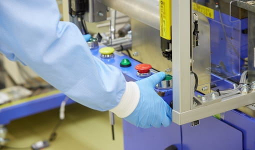
The customer is applying components by hand.
Just looking at this provides a lot of information.
The liner looks hard to peel.
It looks hard to hold with tweezers.
Alignment is taking time.
Air bubbles are being pushed out with fingers.
In other words, operators’ movements tell us improvement points for component design.
■ Where Operators Make Corrections, There Is Room for Improvement
Every time, the operator
bends it slightly,
changes the angle,
presses again,
and adjusts the position.
These movements have reasons.
The material may be hard to handle,
the drawing shape may not suit the process,
or the supply method may be poor.
In other words, observing the movements of skilled workers reveals challenges that can be solved on the component side.
■ Look at Why Jigs Are Used
The customer uses a complex application jig.
Why is it needed?
There may be reasons such as
the component is soft,
positional accuracy is strict,
or the shape is hard to identify.
So by adding
positioning holes,
asymmetric shapes,
and carriers,
the jig may be simplified.
In other words, when a processing company understands the customer’s process,
it can lead to proposals that simplify even equipment and jigs.
■ Look at How the Liner Is Peeled
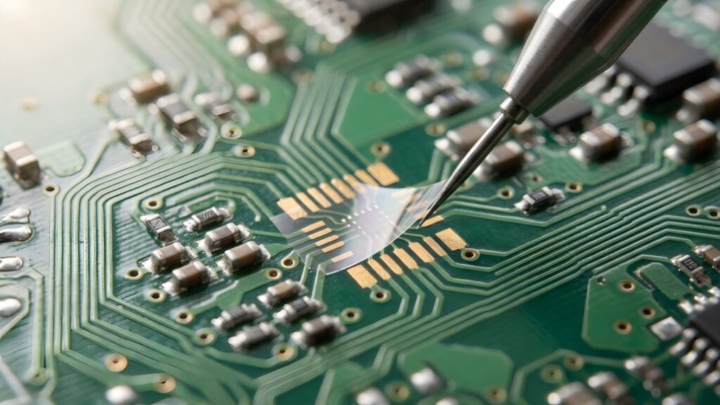
The operator peels the liner.
Searching for the edge with a fingernail.
Using tweezers.
Taking several seconds to peel one.
In this case, improvement may be possible through processing such as
adding a peel tab,
dividing the liner,
or adding a back slit.
In other words, parts that do not remain in the product also have improvement value.
■ Peel Tabs Are Small but Highly Valuable
It has nothing to do with the performance of the finished component.
But with just one peel tab,
work time becomes shorter,
the component is less likely to be damaged,
and the application position becomes stable.
In other words, by looking at the customer’s process, process functions not on the drawing can be added.
■ Look at the Application Direction
From which direction is the customer applying it?
All at once.
From the edge.
With a roller.
This changes how air bubbles form.
It may be worth adding
slits
and air-release openings
to the component shape.
In other words, application movement and processed shape are considered together.
■ If the Customer Is Removing Air Bubbles, That Is a Process Signal
Pressing many times with a roller every time.
Pushing air bubbles outward with fingers.
If this work exists, there is likely room for improvement somewhere in
the material,
adhesive composition,
shape,
or application method.
In other words, the effort on the floor is feedback for component design.
■ If Alignment Takes Time, Consider Whether Shape Can Solve It
Transparent component.
The reference cannot be seen.
The operator adjusts many times.
So
positioning holes,
outer shape references,
and asymmetric notches
are added.
In other words, a processing company can not only raise accuracy, but also create shapes that make accuracy easy to achieve.
■ The Value of Looking at Customer Equipment
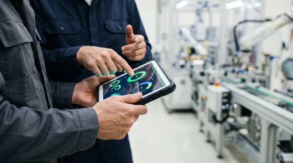
Automatic application equipment.
Robots.
Image recognition.
Pressing equipment.
These are looked at.
Then it becomes clear
at which position the component is picked,
from which direction it is peeled,
where it is picked up by suction,
and at what speed it is applied.
In other words, looking at the customer’s equipment is learning the design conditions on the component side.
■ Working Back from Equipment Specifications to the Component
Suction head width 10 mm.
Component width 5 mm.
As is, it cannot be picked up by suction.
Then
a carrier
or process tab
is provided.
In other words, the mindset changes from “Can this component be used on the equipment?” to
“How do we make a component that can be used on this equipment?”
■ Working Back from Image Recognition to the Shape
The equipment camera
has difficulty recognizing transparent film.
So
recognition holes,
marks,
and carrier contours
are added.
In other words, rather than only improving camera performance, there is also the method of changing the component so it is easy for the camera to recognize.
■ Considering Component Design from Equipment Takt
5 seconds per application.
Required takt is 1 second.
Then the process does not work.
If the causes are
liner peeling,
position correction,
and air bubbles,
they may be improvable on the component side.
In other words, by looking at the customer’s process,
processed components become a target for productivity improvement.
■ Automation Sometimes Goes Back to Component Design
Making equipment higher-performance.
Making robots faster.
These alone have limits.
If the component is made
easier to peel,
easier to pick up by suction,
easier to recognize,
and easier to apply,
the equipment itself can sometimes be simplified.
In other words, part of automation can be solved through component design.
■ Summary of Part 1: Good Components Come from "How They Are Used," Not from Drawings
A drawing specifies outer shape and tolerances.
However, it does not say
why that hole is needed
or why that tolerance is strict.
That is why
ask about the purpose,
look at manual application work,
look at the movements operators use to make corrections,
and look at the equipment’s suction, recognition and takt.
Then process functions not on the drawing become visible, such as
peel tabs,
positioning holes,
air release,
and carriers.
In other words, what we looked at in Part 1 is the idea that what the customer is buying is not a processed product but “a function that works,” and supporting that with the form of the component.
In Part 2, we widen the view further and consider the customer’s process before and after application, and proposals that reorganize the process itself.
Column Supervisor: Koji Kakumoto (President, OTIS Co., Ltd.)
After studying abroad and working in planning and development at a trading company, he joined OTIS Co., Ltd. in 2011. While primarily working in the Corporate Planning Department, he has also served concurrently in manufacturing and technical divisions, and since 2018 has served as President, working to drive business growth and strengthen the organization.
This article is a general technical explanation intended for educational purposes and does not refer to any specific company, product, or technology.