
【1】What Is Electro-Thermal Coupling?
The definition is simple.
Evaluating electrical characteristics and thermal characteristics at the same time.
Evaluation targets are:
・Amount of heat generated
・Temperature distribution
・Current density
・Resistance change
・Progression of degradation
In other words, it is technology that analyzes the chain reaction of:
Current → heat generation → resistance change → further heat generation
【2】Why Coupled Evaluation Is Necessary
There are three reasons.
① A sharp rise in power density
In AI chips: several hundred watts per chip
Locally: several W/mm²
② Current concentration due to scaling
Wiring cross-sectional area shrinks → current density increases.
③ Approaching the limits of heat dissipation
Even TIMs and heat spreaders cannot fully remove the heat.
Result:
Electrical problems lead directly to thermal problems.
【3】Typical Heat Generation Mechanisms
The main cause is Joule heating.
Joule Heat
P = I²R
It increases rapidly (with the square of the current) as current increases.
Switching Losses
During high-speed operation:
・Charge/discharge losses
・Gate losses
Heat from Leakage Current
Leakage increases with scaling.
Heat is generated even in standby.
Heat from Contact Resistance
Occurs in bumps, TSVs, and RDL.
【4】How Temperature Affects Electrical Characteristics
Typical examples of changes with rising temperature:
・Increased resistance → larger voltage drop
・Lower mobility → reduced performance
・Increased leakage current → higher power consumption
・Threshold voltage variation → risk of malfunction
In other words: temperature is a factor in performance degradation.
【5】Typical Failure Mechanisms
Many failures involve both heat and electricity.
Electromigration (EM)
Atoms migrate under high temperature × high current.
Wiring breaks.
Thermal Runaway
Heat generation → lower resistance → increased current → more heat generation.
Runaway destruction.
Accelerated TDDB
Insulating film breakdown is accelerated by temperature.
Accelerated Solder Fatigue
Degradation is promoted by thermal cycling.
【6】Evaluation and Analysis Methods
For coupled evaluation, analysis of one side alone is insufficient.
Electrical Analysis
・IR drop
・Current density
Thermal Analysis
・Temperature distribution
・Heat flux
Coupled Analysis
Both are calculated simultaneously.
Example tools:
・FEM analysis
・CFD analysis
・Coupled electromagnetic field analysis
【7】Relationship with Package Design
Heat path design is the key.
Main heat flow:
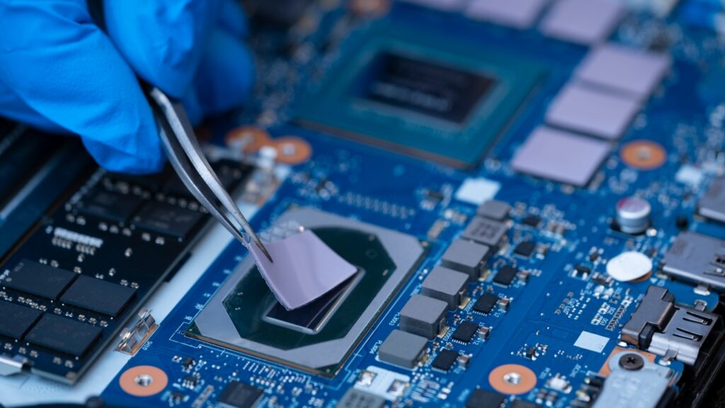
Chip → bumps → substrate → heat spreader → cooling system
Influencing factors:
・TIM thermal resistance
・Bump density
・TSV placement
・Heat spreader material
In other words: the package is a heat dissipation circuit.
【8】Characteristics of the AI Chip / HBM Era
There are three characteristics.
① Local hot spots
Concentration of compute blocks.
② Memory placed close by
HBM impedes heat spreading.
③ 3D stacked structures
Heat has difficulty escaping.
Result: temperature non-uniformity determines performance.
【9】Design Countermeasures
Typical examples:
・Stronger power wiring → reduced IR drop
・Optimized bump density → improved heat dissipation
・High-thermal-conductivity TIMs → reduced thermal resistance
・Larger heat spreaders → heat spreading
・Integrated liquid cooling → for AI chips
【10】Relationship with Volume Production and Reliability
Coupling problems tend to surface after volume production begins.
Example symptoms:
・Reduced frequency
・Increased power consumption
・Thermal runaway
・Early failures
Therefore: coupled analysis at the design stage is essential.
【11】Future Technology Trends
Areas of attention:
● Electro-thermal co-design for chiplets
● Thermal analysis of 3D stacking
● Thermal evaluation of co-packaged optics
● Analysis of liquid-cooled packages
● AI-based thermal prediction
The design domain is expanding from electrical alone → thermal coupling → system coupling.
【12】Summary
・Electricity and heat are interdependent
・Heat generation increases with current density
・Temperature degrades electrical characteristics
・They are directly linked to failure factors such as EM and thermal runaway
・It is the most important evaluation area for advanced AI chips
Comprehension Check
1.Why is electrical evaluation alone insufficient?
2.Explain the formula for Joule heating.
3.How does thermal runaway occur?
4.Why is thermal design difficult for 3D stacked chips?
Column Supervisor: Koji Kakumoto (President, OTIS Co., Ltd.)
After studying abroad and working in planning and development at a trading company, he joined OTIS Co., Ltd. in 2011. While primarily working in the Corporate Planning Department, he has also served concurrently in manufacturing and technical divisions, and since 2018 has served as President, working to drive business growth and strengthen the organization.
This article is a general technical explanation intended for educational purposes and does not refer to any specific company, product, or technology.