■ What Generates Heat in Energy Equipment?
Typical heat sources include
● IGBTs
● SiC
● GaN
● MOSFETs
● Diodes
● Transformers
● Inductors
● Capacitors
● Busbars
● Batteries
● Connection terminals
All of these generate heat in the process of converting, carrying or storing electricity.
In particular, the more large amounts of power are handled in small equipment, the higher the heat generation density becomes.
■ Power Semiconductors Are at the Center of Thermal Design
In inverters and converters,
power semiconductors
are important.
They switch electricity ON and OFF at high speed,
convert between direct and alternating current,
change voltage,
and control power.
However, losses occur every time they switch.
Those losses become heat.
In other words,
the more power conversion performance is raised, the more important thermal management of power semiconductors becomes.
■ Will SiC and GaN Eliminate Heat Generation Problems?
Next-generation power semiconductors such as SiC and GaN are advantageous for higher efficiency and higher frequencies.
If losses can be reduced, heat generation can also be reduced.
However,
this does not mean heat problems themselves disappear.
As efficiency increases,
equipment is made even smaller
and even higher in output.
As a result,
heat generation density per unit volume
may become higher.
In other words, the higher semiconductor performance becomes,
the more sophisticated cooling requirements become.
■ Miniaturization Reduces the Area for Releasing Heat
For example, a large inverter is miniaturized.
Components come closer together.
The cooling area also becomes smaller.
Airflow paths also become narrower.
Then,
even with the same heat generation,
heat concentrates more easily.
In other words,
miniaturization and thermal management are not easily compatible.
■ Power Semiconductors Release Heat to Cooling Plates
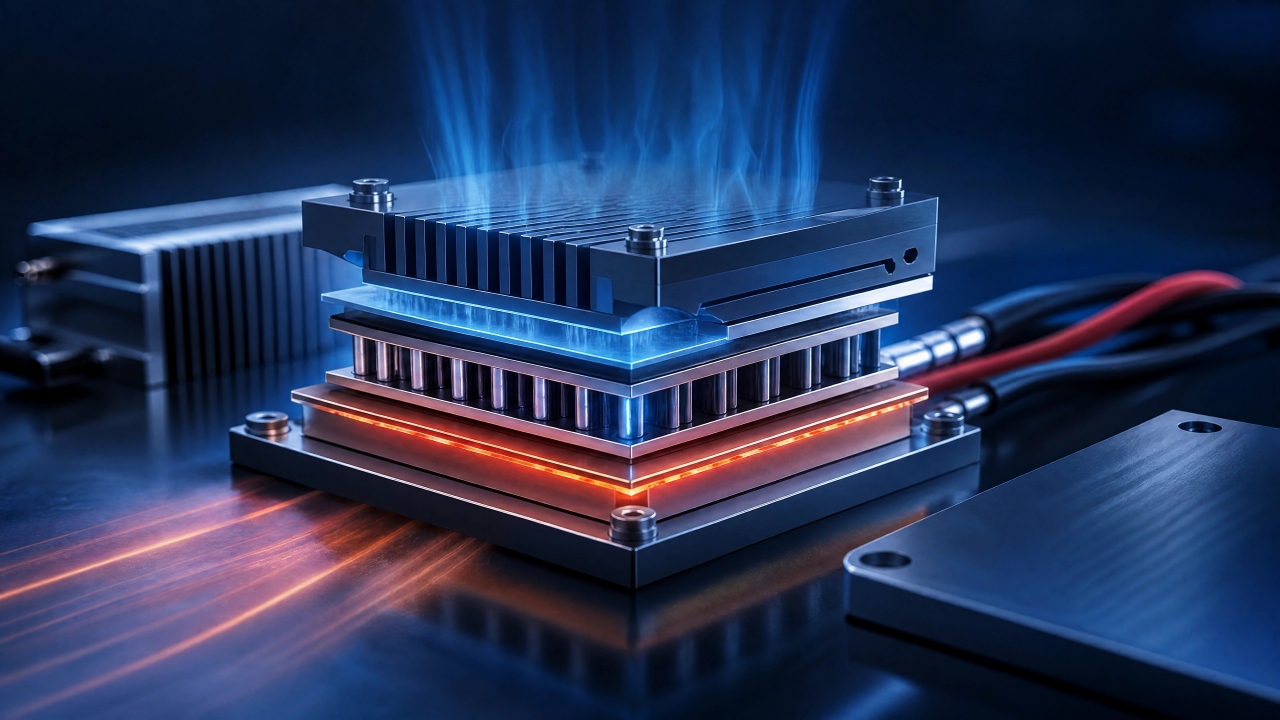
High-output power semiconductors use a heat path such as
Semiconductor
↓
Insulating layer / TIM
↓
Metal base
↓
Cooling plate
↓
Air or coolant
What matters here is between the semiconductor and the cooling plate.
Even with a high-performance cooling plate,
if the thermal resistance of the interface is large, it will not cool sufficiently.
■ "Passing Heat While Insulating" Is One of the Biggest Challenges
In power semiconductors, the structure is:
the cooling plate is metal.
The semiconductor side carries high voltage.
That is why the contradictory requirements arise that
electrically, you want to insulate.
Thermally, you want close contact.
Here,
● Insulating TIM
● Ceramic substrates
● Insulating films
● Thermally conductive insulating sheets
are used.
■ Making Insulating Material Thicker Makes It Harder for Heat to Escape
To increase insulation performance, one wants to make the insulating material thicker.
However, in general, as thickness increases, the distance heat travels also increases.
In other words, there is the relationship:
Thick
→ More margin for insulation
→ Tends to be disadvantageous for heat
Thin
→ Advantageous for heat
→ Stricter requirements for insulation reliability
That is why, in energy equipment, design that
minimizes thermal resistance as much as possible while securing the necessary insulation performance
is important.
■ Burrs and Foreign Matter Destroy Insulation Performance
When using thin insulating films,
● Metal burrs
● Foreign matter
● Protrusions
● Scratches
become major problems.
Even if the material itself has sufficient insulation performance,
performance changes if it is scratched after processing.
In other words, it is necessary to look not only at
the insulation performance of the material, but at
the insulation performance as a processed component.
■ Air Bubbles and Lifting Are Also Problems in TIM
When TIM is used between a power module and a cooling plate,
● Air bubbles
● Warping
● Thickness differences
● Insufficient contact pressure
increase thermal resistance.
The higher the output, the more easily even a local increase in thermal resistance creates a hot spot.
In other words, there are cases where
a small contact defect limits the performance of large power equipment.
■ Thermal Cycling Becomes a Major Problem
In energy equipment,
high load,
low load,
stopping,
and restarting
are repeated.
Each time,
it heats up
and cools down,
repeatedly.
Then
● Semiconductors
● Metals
● Ceramics
● Solder
● Bonding agents
● Insulating materials
each expand and contract at different rates.
Through this repetition, thermal stress arises.
■ Lowering Temperature Alone Is Not Enough
Even if the average temperature is low,
repeating
50°C
↓
100°C
↓
50°C
in a short time may place large stress on materials.
In other words, in energy equipment,
not only maximum temperature, but temperature differences and the number of temperature changes are important.
■ Adhesive Layers and Laminated Interfaces Can Become Weak Points
When dissimilar materials are laminated,
their thermal expansion coefficients differ.
When temperature cycles are repeated,
stress is applied to the interfaces.
As a result,
● Peeling
● Cracks
● Lifting
may occur.
If it lifts, thermal resistance increases.
In other words,
mechanical degradation leads to thermal performance degradation.
■ Summary
As we have seen, the heat problems of energy equipment arise centered on power semiconductors.
Converting power always creates losses, and much of those losses becomes heat.
Even if efficiency rises with next-generation power semiconductors such as SiC and GaN, equipment moves toward further miniaturization and higher output, so the difficulty in terms of heat generation density remains.
And energy equipment has strong requirements precisely because it handles high voltages.
You want to release heat to the cooling plate.
But electricity must never pass.
The core is how to achieve both of these contradictory conditions, “pass heat, stop electricity,” through the thickness design of insulating materials and TIM.
Furthermore, thermal cycles that repeat high load, low load and stopping quietly weaken adhesive layers and laminated interfaces through the differences in expansion and contraction of dissimilar materials.
Even if things look fine initially, repetition may eventually lead to peeling or cracks.
In Part 2, we look at how elements such as EMI, waterproofing and long-term reliability overlap with these heat and insulation challenges, and how they are handled in actual applications such as ESS, charging equipment and hydrogen equipment.
And we look at how this is made to work in volume production, and what role OTIS plays.
Column Supervisor: Koji Kakumoto (President, OTIS Co., Ltd.)
After studying abroad and working in planning and development at a trading company, he joined OTIS Co., Ltd. in 2011. While primarily working in the Corporate Planning Department, he has also served concurrently in manufacturing and technical divisions, and since 2018 has served as President, working to drive business growth and strengthen the organization.
This article is a general technical explanation intended for educational purposes and does not refer to any specific company, product, or technology.