■ In Automation, the Component Itself Becomes an Equipment Part
In manual work, people look at the component and judge.
If it is slightly misaligned, they fix it.
If it is hard to peel, they change the angle.
If it is soft, they hold it carefully.
But automated machines are different.
The component is in a fixed place.
It has a fixed shape.
It is in a fixed posture.
It peels with a fixed force.
They operate on these premises.
In other words, in automation, the thermal management component itself becomes
an interface part for the equipment to handle.
■ "Can Be Delivered as Loose Pieces" Is Not Necessarily Volume Production Value
Small TIM pieces are die-cut one at a time.
Put in bags.
Delivered to the customer.
For small-volume prototyping, this is no problem.
But in volume production,
taking them out of the bag,
checking front and back,
checking orientation,
and aligning the position
are needed.
The larger the quantity, the more man-hours increase.
That is why, when the customer wants to automate,
being able to feed it directly into the equipment rather than supplying loose pieces
can be more valuable.
■ Reel Supply Is a Typical Method of Automation
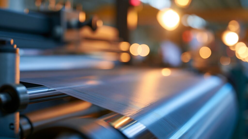
Small components are arranged at a constant pitch on a carrier and supplied in long reel form.
While feeding the reel, the equipment can
peel the component,
pick it up,
correct its position,
and apply it to the workpiece.
This has the advantages that
● Component orientation can be aligned
● Components can be taken from a fixed position
● Continuous supply is possible
● People do not need to line up components
In other words, reel supply is not just a packaging method.
It is a method of connecting components to automated equipment.
■ Not Everything Can Be Automated Just by Making It into a Reel
It does not end with lining components up on a reel.
For example,
the component pitch varies.
Components move on the carrier.
The peeling force is too strong.
Components warp due to winding curl.
If there are such problems, automation is not stable.
In other words, reel supply requires design including
● Pitch
● Carrier width
● Winding direction
● Liner
● Peeling force
● Component posture
■ If It Cannot Be Peeled, Automation Does Not Even Begin
In the automated application process, the component must first be peeled from the liner.
But with high-tack materials or soft TIM, the component can remain strongly on the liner.
People can
hold a corner,
peel slowly,
or peel from another direction.
But automated machines need to peel stably under fixed conditions.
In other words,
peelability is also part of component performance.
■ Peeling Force That Is Too Strong or Too Weak Is a Problem
If the peeling force is strong,
● The component may remain
● It may deform
● It may stretch
● It may lead to equipment stoppage
On the other hand, if it is too weak,
● The component may shift during transport
● It may move within the reel
● It may come off midway
In other words, what is needed is neither strong nor weak peeling.
It is stable peeling force suited to the volume production equipment.
■ The Liner Material Also Governs Automation Performance
Even with the same adhesive material, peeling behavior changes with
paper-based liners,
PET liners,
and liners with different surface treatments.
Furthermore,
● Rigidity
● Thickness
● Chargeability
● Winding curl
also differ.
That is why, even though the liner does not remain in the product, it is very important in automation.
Material that becomes unnecessary for the customer becomes an important part in volume production equipment.
■ Components Can Deform During Peeling
Thin TIM.
Graphite.
Long, narrow insulating films.
These deform easily from the force during peeling.
For example, long, narrow graphite is peeled from the liner.
It is pulled from the end.
At that moment, the component stretches or bends.
The equipment thinks it picked up the correct position, but the actual shape of the component has changed.
Then application accuracy deteriorates.
In other words, it is necessary to check not only the shape after processing, but whether the shape can be maintained even during peeling.
■ If It Cannot Be Picked Up, It Cannot Be Transported
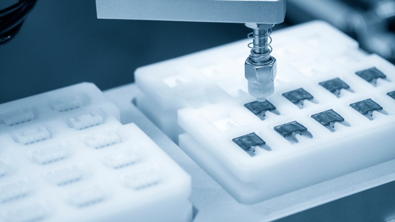
In many automated application machines, components are held with vacuum suction heads.
However, with
● Foams
● Porous materials
● Soft TIM
● Materials with large surface irregularities
vacuum leaks and stable pick-up may not be possible.
Components that cannot be picked up
drop,
tilt,
and shift position.
That is why, even if unrelated to thermal performance, it becomes a big problem in volume production.
■ With Thin Components, Suction Itself Becomes a Cause of Deformation
When a thin film is strongly vacuum-picked, the material can be drawn into the suction holes.
Then the component ripples.
It warps.
If applied in that state, it leads to
● Air bubbles
● Wrinkles
● Misalignment
In other words, there are cases where
the force used to hold it destroys component quality.
In automation, the suction method and component design must be considered together.
■ There Is Also Compatibility with the Suction Head
A single suction head cannot necessarily handle all materials.
For example, there are suitable and unsuitable materials depending on the method:
large flat suction,
small point suction,
porous suction,
electrostatic suction,
and so on.
In other words,
“how to hold this component”
is not just the equipment manufacturer’s problem.
It is worth considering from the stage of deciding materials and shapes.
■ If It Cannot Be Recognized by Images, It Cannot Be Applied Accurately
In automated application, cameras often recognize the positions of components and workpieces.
But some materials are hard to recognize.
For example,
transparent films,
black graphite,
mirror-finish metal foils,
and transparent adhesives.
These may
have outlines that are hard to see,
reflect light,
and blend into the background.
As a result, position correction on the equipment side becomes unstable.
■ Even If Unnecessary Thermally, Recognition Features May Be Needed
For example, considering only thermal performance, a perfect rectangle is fine.
But for image recognition,
● Small notches
● Recognition holes
● Asymmetric parts
● Tabs
are added.
This makes it easier for the equipment to recognize the component’s orientation.
In other words, in volume production,
shapes that are unnecessary for function can be necessary for automation.
This is an important point to know at the design stage.
■ Transparent Materials Can Be Especially Hard to Recognize Automatically
Transparent insulating films can be very convenient as products.
But from the camera’s view, the difference from the background is small.
Depending on lighting conditions, the outline is barely visible.
Then problems occur:
the component cannot be found,
and the position cannot be corrected.
In this case, measures such as
changing the shape,
changing the carrier color,
or adding marks
are sometimes used.
In other words, in automation, it is necessary to design the recognition system including not only the component itself but also the background.
■ Symmetrical Shapes Cause Misrecognition
Perfectly symmetrical shapes make orientation hard to tell even for the equipment.
For example, front and back differ, but the outline is the same.
Then even if it is applied the wrong way, it is hard to detect.
So mistake-proofing is done, such as
changing the shape at just one point,
making hole positions asymmetric,
or adding a tab.
In volume production automation, making shapes that cannot be mistaken is also quality design.
■ Long, Narrow Shapes Raise Automation Difficulty
To release heat sideways, graphite and metal foil are sometimes designed long and narrow.
This is rational as thermal design.
But in automation, problems tend to occur such as
● Bending during peeling
● Being hard to pick up
● Rotating easily
● Wrinkling during application
In other words,
a thermally good shape can be a difficult shape for equipment.
Design optimization is needed here.
■ Narrow Bridge Sections Can Tear During Transport
Irregularly shaped insulating films and the like sometimes have shapes that leave narrow sections.
At rest, there is no problem.
But when stress is applied during peeling, pick-up and transport, those narrow sections may stretch or tear.
That is why it is necessary to consider all of
the shape needed during product use,
the shape needed during processing,
and the strength needed during transport.
■ The Idea of Leaving a Carrier
With very soft or thin components, peeling them in their finished shape can cause deformation.
So there is a method of leaving a carrier portion around them to support the component until just before application.
Or multiple components are held on a single carrier.
This can improve
transport stability,
positional accuracy,
and peeling stability.
In other words, for processing shapes, process shapes that do not remain in the final product are also important.
■ Half-Cutting Is a Good Match for Automation
Adhesives and films are half-cut and supplied with the liner left in place.
Then the components can maintain their position on the liner.
The equipment can peel them one at a time at the necessary timing.
In other words, half-cutting is
not just a processing method, but also
a processing technology for making automated supply work.
■ Component Pitch Affects Equipment Takt
If the component pitch on the reel is too large, material waste increases.
If it is too small, problems occur such as
peeling areas interfering,
insufficient space for pick-up,
and difficulty in equipment recognition.
In other words, pitch must be decided not only by material yield, but by
balance with equipment motion.
■ Carrier Width Also Becomes an Equipment Specification
A narrow carrier can reduce material usage.
But transport stability may worsen.
A wide carrier is easy to transport.
But it affects material cost and equipment size.
In other words,
design that lowers component unit price and design that raises equipment stability do not necessarily coincide.
Overall optimization is needed here too.
■ Just Getting the Winding Direction Wrong Can Keep It from Fitting the Equipment
In reel supply,
component front and back,
winding inside or outside,
and leading direction
are important.
The customer’s equipment may only be able to take components in a fixed orientation.
In other words,
it is not the case that
“it’s the same component, so either orientation is fine.”
The winding direction itself can be a product specification.
■ Reel Diameter Can Also Affect Components
If the reel diameter is small, thin-film materials can acquire a strong bending habit.
Warping remains even after the component is taken out.
Then problems occur:
it is hard to pick up,
and it is hard to bring into full-surface contact with the workpiece.
In other words, in reel design, it is necessary to look not only at packaging size but at the bending characteristics of the component.
■ Static Electricity Also Stops Automation
When films and liners are peeled at high speed, static electricity may be generated.
Static electricity may cause
the component to fly from the peeling position,
re-adhere to the liner,
attract foreign matter,
or stick to the transport head.
Thinner films are especially susceptible.
In other words, in automation,
not only mechanical accuracy but also static electricity control is important.
■ Foreign Matter Also Causes Equipment Stoppage
Debris comes off the edges of components.
Adhesive strings.
Material fragments remain during peeling.
Then problems occur such as
adhering to the suction head,
interfering with image recognition,
and transferring to the next product.
In other words, deterioration in processing quality may not only cause a single defect but spread defects to the entire equipment.
■ When Adhesive Squeezes Out, Automated Machines Get Dirty
Adhesive can squeeze out from the edges due to high temperature and pressure.
If continuous processing is done in that state,
adhesive adheres to
rollers,
guides,
and suction heads.
Then equipment stoppage and cleaning become necessary.
In other words, in volume production, what matters is not only the application performance of a single piece, but whether the equipment can run for long periods without getting dirty.
■ Summary of Part 1: In Automation, the Component Itself Becomes an Equipment Part
With manual work, people can look and judge.
If it is misaligned, they fix it. If it is hard to peel, they change the angle.
But automated machines operate on the premise of a fixed shape, a fixed posture and a fixed peeling force.
Components that deviate from those premises cannot be handled, even if their performance is high.
It cannot be peeled.
It cannot be held.
Even if it can be held, it deforms.
The camera cannot find it.
Long, narrow shapes bend.
It warps from winding curl.
It flies due to static electricity.
Adhesive dirties the equipment.
None of these relate to thermal conductivity.
But all of them become fatal in volume production.
In other words,
the thermally optimal shape is not necessarily optimal for equipment.
In Part 2, we look at the decisions beyond this.
Takt time. Equipment stoppage rate. Total cost.
And actual failure cases, and the areas a processing company can take on.
Column Supervisor: Koji Kakumoto (President, OTIS Co., Ltd.)
After studying abroad and working in planning and development at a trading company, he joined OTIS Co., Ltd. in 2011. While primarily working in the Corporate Planning Department, he has also served concurrently in manufacturing and technical divisions, and since 2018 has served as President, working to drive business growth and strengthen the organization.
This article is a general technical explanation intended for educational purposes and does not refer to any specific company, product, or technology.