
■ Why Are Thermal Management Components Hard to Automate?
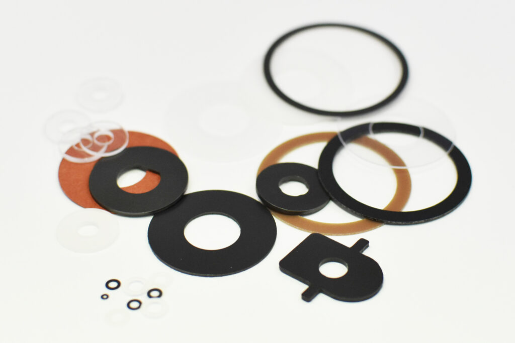
Thermal management components have many features that are poorly suited to automation.
Soft TIM.
Thin graphite.
Transparent insulating film.
Long, narrow metal foil.
Tiny adhesive components.
These are
hard to grip,
hard to see,
easy to deform,
and hard to peel.
In other words, automation requires “ease of handling,” which is separate from material performance.
What automation requires is functional performance + handling performance.
■ Loose Supply Leaves Human Judgment
Small TIM is delivered in bags.
The customer must
take one,
check front and back,
check orientation,
align the position,
and apply it.
Operators correct naturally.
If it is slightly bent, they straighten it.
If two are stuck together, they separate them.
But it is hard to have automatic machines make such judgments.
In other words, even if loose parts are complete as components,
the connection to the volume production process may not be complete.
■ Reel Supply "Gives Components an Address"
On a reel, components are arranged according to rules such as
what mm pitch,
which orientation,
and which position.
From the equipment’s point of view, the state becomes
“the next component is always here.”
This is very important.
That is because automation requires, in addition to the accuracy of the components themselves, reproducibility of where the components are located.
■ Reel Supply Can Fix Orientation
Irregular-shaped components have orientation.
There is
top and bottom,
left and right,
and front and back.
These tend to get mixed with loose parts.
On the other hand, if arranged in a fixed orientation on a reel, the equipment can reduce orientation-checking processes.
In other words, reel supply is also a technology for standardizing component posture.
■ The Smaller the Component, the Higher the Value of Reel Supply
A 50 mm square component is easy to handle by hand.
At
3 mm square
or 5 mm square,
problems increase:
hard to pick up,
dropped,
two stuck together,
sticking due to static electricity.
In other words, the more components are miniaturized,
the harder “being able to handle them” becomes than “being able to make them.”
Reel supply is one way to solve this problem.
■ Thin-Film Components Also Work Well with Reel Supply
A thin film is peeled one at a time.
It curls.
It wrinkles.
It sticks to fingers due to static electricity.
But if held on a liner, it is easier to maintain its shape.
If the equipment applies it right after peeling, the time spent being transported in the air can also be shortened.
In other words, reel supply becomes a way to hand over thin-film components to volume production processes in a stable posture.
■ Reel Conversion Is Not Just "Winding"
Components are lined up on a liner.
Wound.
That alone does not enable automation.
What is needed is to decide
pitch,
carrier width,
liner material,
peel force,
winding direction,
winding diameter,
and component position.
In other words, reel supply itself becomes a design task.
■ Pitch Design Is Important
Widening the pitch between components.
Easier for the equipment to pick up.
But more carrier material is used.
The reel length also becomes longer.
Narrowing the pitch.
Material yield is good.
But
there is less space for peeling,
the suction head may interfere,
and camera recognition may be difficult.
In other words, pitch must be decided by the balance between material yield and equipment stability.
■ Carrier Width Is Also Matched to Equipment Specifications
A narrow carrier.
Material usage decreases.
However,
it meanders easily,
rigidity is insufficient,
and it is hard to guide.
A wide carrier.
Transport is stable.
But material usage increases.
In other words, the minimum width is not necessarily optimal.
What is needed is a width the equipment can transport stably.
■ Liner Material Changes Suitability for Automation
PET liners,
paper liners,
and differences in surface treatment
change
rigidity,
peel force,
chargeability,
and dimensional stability.
In other words, a liner that does not remain in the product greatly affects equipment performance.
This is one of the characteristics of components for automation.
■ Designing Peel Force
If adhesive components do not peel from the liner, the equipment stops.
But if they peel too easily, they fall off during transport.
In other words, what is needed is not
strong adhesion
or weak adhesion.
It is stable peeling behavior that matches equipment conditions.
■ Component Behavior Changes with Peel Angle
Peeling with the liner folded back nearly 180 degrees,
versus peeling at a small angle,
applies different forces to the component.
Especially with
thin graphite,
narrow TIM,
and soft adhesive components,
the force during peeling deforms the component.
In other words, in reel component design, it is necessary to consider even how the material is peeled.
■ Matching Peel Direction and Shape
A long, narrow component is peeled from the long side.
Large deformation occurs.
It is peeled from the short side.
It is stable.
This can happen.
In other words, even for the same component,
just changing its orientation on the liner by 90 degrees can change mass producibility.
That is why the arrangement direction must not be decided by material yield alone.
■ Making Shapes That Can Be Picked Up by Suction
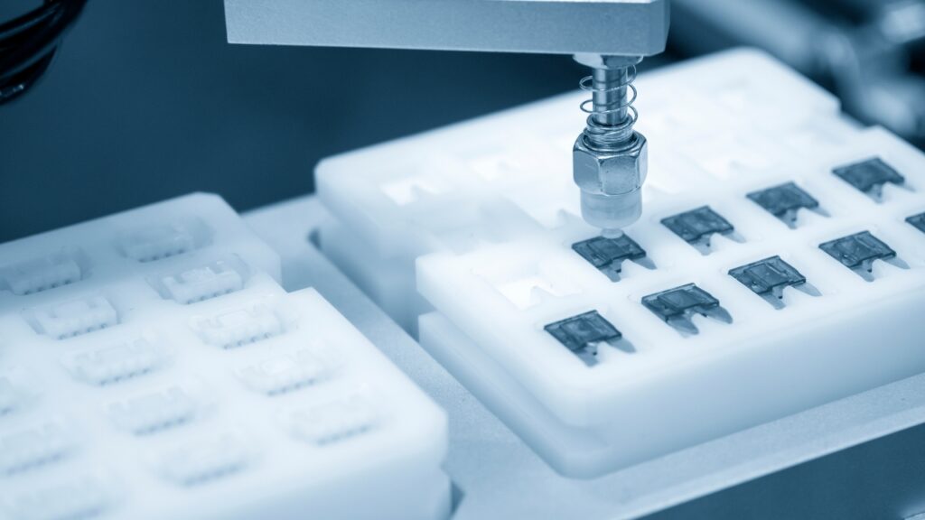
Automatic machines often use vacuum suction.
But if the component has a large hole in the center,
is too narrow,
or is porous,
it is hard to pick up.
So methods are considered such as
temporarily leaving a carrier,
adding suction tabs,
and securing suction area.
In other words, not only the product shape but the transport shape is designed.
■ The Concept of Process Tabs
Not needed in the final product.
But needed for automation.
For example,
suction tabs,
recognition tabs,
and peeling tabs
are added.
They are removed after application.
In other words, a component has a shape after completion and a shape needed during the process.
Thinking of these two separately is important in automation design.
■ Transporting with the Carrier Left On
Very thin film.
Soft TIM.
They cannot maintain their shape on their own.
So the surrounding unnecessary parts are deliberately left.
They support it as a carrier.
At the customer’s application, only the necessary part is peeled.
In other words, it is also possible to turn unnecessary parts into process functions.
■ Half-Cutting Is the Foundational Technology of Reel Supply
Only the product layer is cut.
The liner is left.
This makes it possible to
hold components at fixed positions,
transport them,
and supply them continuously.
In other words, half-cutting is not just a processing method, but a structure for establishing automated supply.
■ Half-Cut Accuracy Affects Automation Stability
The cut is too deep.
The liner is damaged.
It breaks during transport.
Too shallow.
The product is not fully separated.
It is pulled during peeling.
In other words, half-cut depth is also an important condition for stable peeling on automatic machines.
■ Waste Removal Also Directly Affects Automation Quality
Unnecessary parts are removed.
But small scraps remain.
They flow into the equipment.
They stick to the suction head.
They interfere with image recognition.
In other words, with reel products, it is necessary
to supply them with unnecessary parts completely removed.
■ Adhesive Stringing Stops Equipment
The component is peeled from the liner.
The adhesive strings.
It sticks to the equipment.
It transfers to the next component.
With long-term operation, the equipment gets dirty.
In other words, even if there is no problem in short-term evaluation,
problems can appear in continuous operation.
In automation,
continuous operation quality matters more than the quality of a single unit.
■ Static Electricity Countermeasures Are Also Needed
Film and liner are peeled at high speed.
Static electricity is generated.
The component may
re-stick to the liner,
stick to the head,
fly off in another direction,
or attract foreign matter.
In other words, with reel supply, it is necessary to consider even
material,
peeling speed,
humidity,
and static elimination.
■ The Lighter the Component, the Greater the Effect of Static Electricity
A metal block does not fly off due to static electricity.
Films of tens of μm are light.
They move with very small forces.
In other words, the more thinning and miniaturization advance,
static electricity can become a dominant factor in volume production processes.
■ Making Shapes Easy to Recognize by Imaging
The equipment sometimes checks
component position,
orientation,
and workpiece position
with cameras.
However,
transparent film,
black graphite,
and mirror-finish metal foil
can be hard to recognize.
So
recognition holes,
notches,
marks,
and carrier contours
are used.
In other words,
making shapes that are easy for machines to find
is also automation support.
■ For Transparent Components, the Carrier Can Be Recognized Instead
Finding the transparent film itself with a camera is difficult.
So reference marks are provided on the liner side.
The equipment estimates the component position from the marks.
In other words, rather than the final component itself,
there is also the idea of creating recognizability with the entire supply body.
■ Preventing Wrong Orientation with Asymmetric Shapes
A perfectly symmetric shape.
To the equipment, it looks the same even when flipped 180 degrees.
But in reality, the adhesive side and functional side differ.
So the notch is changed in only one place.
Holes are made asymmetric.
Then the equipment can determine orientation.
In other words,
a tiny shape change becomes a major mistake-proofing (poka-yoke) measure.
■ Changing Component Shape for Automation
The shape per the customer’s drawing is correct as a product.
But it is hard to handle for automation.
In this case,
within a range that does not affect function,
changing corner radii,
adding tabs,
changing widths,
and adding recognition shapes
are proposed.
In other words, there is
value in a processing company proposing DFM premised on automation.
■ "Making It Work with Equipment" Alone Can Be Costly
The component is hard to handle.
On the equipment side,
complex suction heads,
high-performance image recognition,
and special robots
are added.
It may be possible.
But equipment costs become large.
On the other hand, sometimes simple equipment can handle it with just a slight change in component shape.
In other words,
simplifying equipment through ingenuity on the component side
is very important.
■ Automation Is Joint Design of Equipment and Components
Only the equipment manufacturer thinks about automation.
The component manufacturer only makes components.
Then problems tend to occur at the boundary.
What matters is reflecting what the equipment side needs, such as
pitch,
peel direction,
suction position,
and recognition method,
in component design.
In other words, automation is
a joint effort of equipment design and component design.
■ Summary of Part 1: Creating a State Where Equipment Is Unlikely to Fail, from the Component Side
Thermal management components have many features poorly suited to automation.
Soft. Thin. Transparent. Long and narrow. Small.
Hard to grip, hard to see, easy to deform, and hard to peel.
That is why what is needed is handling performance in addition to functional performance.
Reel supply is one answer to that.
Components are lined up at a fixed pitch, in a fixed orientation and at a fixed position.
From the equipment’s point of view, the next component is always there.
But it does not end with winding.
If the pitch is too narrow, the suction head interferes.
If the carrier is too narrow, it meanders.
Just changing the liner changes both peel force and chargeability.
If the peel angle does not match, the component deforms on the spot.
For long, narrow components, just changing orientation by 90 degrees changes mass producibility.
Furthermore, if it cannot be picked up by suction, it cannot be transported.
If it cannot be found, it cannot be applied.
That is why process tabs are added, recognition holes are opened, and shapes are made asymmetric.
Even if not needed in the final product, there are shapes needed during the process.
In other words,
automation is not just the equipment side’s job.
Just slightly changing the component shape can sometimes simplify the equipment.
In Part 2, we look at which supply format to actually choose,
and how to protect it until it reaches the customer.
Column Supervisor: Koji Kakumoto (President, OTIS Co., Ltd.)
After studying abroad and working in planning and development at a trading company, he joined OTIS Co., Ltd. in 2011. While primarily working in the Corporate Planning Department, he has also served concurrently in manufacturing and technical divisions, and since 2018 has served as President, working to drive business growth and strengthen the organization.
This article is a general technical explanation intended for educational purposes and does not refer to any specific company, product, or technology.