■ What Is Thermal Simulation?
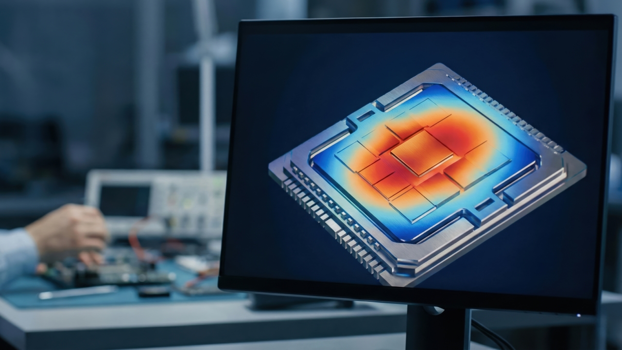
Thermal simulation is a method of predicting by calculation, within a product or component,
● Where heat is generated
● In which direction heat flows
● Where heat concentrates
● How much the temperature rises
It quantifies phenomena such as heat conduction, convection, and radiation, and checks heat problems at the design stage.
Because multiple materials and structures can be compared without making every prototype, it helps shorten development periods and improve designs.
■ Simulation Is Extremely Important
Simulation has great value.
For example, it enables
● Predicting hot spots
● Comparing the effects of material changes
● Visualizing heat dissipation paths
● Comparing heat sink shapes
● Examining cooling conditions
● Narrowing down design options
Especially in products with many heat sources and complex internal structures, such as AI servers and 3D semiconductors, it is difficult to understand the whole without simulation.
However, treating simulation results as the actual device’s performance as is, is dangerous.
■ Simulation Is Determined by Its Preconditions
In simulation, preconditions are always set.
For example,
● Amount of heat generated
● Material properties
● Component dimensions
● Contact state
● Ambient temperature
● Air velocity
● Cooling water temperature
● Emissivity
● Boundary conditions, and so on.
If these settings differ from reality, the calculation results will also differ from reality.
In other words, the accuracy of a simulation is greatly influenced not only by the performance of the calculation software, but also by the correctness of the input conditions.
■ The Amount of Heat Generated May Differ from Reality
In simulation, the power consumption of heat-generating components is set as the amount of heat generated.
In actual products, however, the amount of heat generated is not necessarily constant.
For example, with GPUs in AI servers, the amount of heat generated changes depending on
● Processing content
● Utilization rate
● Operating frequency
● Power control
● Ambient temperature
● Thermal throttling
In EVs and robots too, the amount of heat generated changes depending on driving conditions, load, and charge/discharge state.
In other words, calculations that assume constant heat generation and
actual devices that keep changing can produce different results.
■ Material Properties Are Not Necessarily Constant
In simulation, the thermal conductivity of a material is often input as a single number.
In reality, however, material properties may change with temperature and condition.
For example,
● Thermal conductivity changes with temperature
● The state of TIM changes with compression ratio
● Resin properties change with humidity
● Adhesive materials harden over time
● Gels deform due to thermal history
In other words, entering a single catalog value may not fully represent the actual usage state.
■ The Directionality of Materials Can Be Overlooked
Graphite and some composite materials have thermal conductivity that differs depending on direction.
They conduct heat well in the in-plane direction.
However, they do not conduct it the same way in the thickness direction.
Unless this directionality is set correctly, simulation results will not match reality.
In other words, even if the material name is the same, which direction’s thermal conductivity is used is important.
■ Setting Contact Thermal Resistance Is Difficult
One of the major causes of the gap between simulation and measurement is
contact thermal resistance.
Even if components appear to be in contact with each other, in reality there are surface irregularities and air layers.
That is why heat has difficulty flowing at interfaces.
In simulation, however, components are sometimes set to be in perfect contact.
Then heat flows well in the calculation.
In the actual device, on the other hand, heat stops due to
● Air bubbles
● Lifting
● Insufficient pressure
● Foreign matter
● Surface roughness
● Application misalignment
In other words, the gap of perfect contact in the simulation, imperfect contact in the actual device arises.
■ Reproducing the Mounted State of TIM Is Difficult
TIM is one of the materials that is difficult to handle in thermal simulation.
The performance of TIM changes with
● Thickness
● Compression ratio
● Softness
● Contact pressure
● Surface condition
● Air bubbles
● Changes over time
In simulation, it is sometimes treated as having uniform thickness, uniform compression, and uniform contact.
In the actual device, however, not everything is uniform.
That is why simply entering the catalog thermal conductivity of TIM may not reproduce the actual interface performance.
■ Dimensional Tolerances May Not Be Included in the Calculation
Design drawings list nominal dimensions.
However, actual components have tolerances.
The height of heat-generating components.
The flatness of cooling plates.
The thickness of heat dissipation sheets.
The thickness of adhesive layers.
Warping of the enclosure.
When these combine, contact pressure and gaps change.
In simulation, however, calculations are often done entirely with nominal dimensions.
In other words, the difference between ideal design dimensions and actual dimensions of mass-produced items becomes the difference from measurement.
■ Modeling Air Layers Accurately Is Difficult
Air layers have a major effect on thermal performance.
However, actual air layers may
● Not have constant thickness
● Have different shapes in different places
● Exist as air bubbles
● Change with compression bonding
● Expand with temperature
It is difficult to put all of these complex air layers accurately into a simulation.
That is why, in the actual device, thermal resistance can be greater than in the calculation.
■ Convection Conditions May Differ from Reality
In air cooling, airflow is important.
In simulation, a constant air velocity or uniform airflow is sometimes set.
Inside actual equipment, however, airflow becomes complex due to
● Cables
● Boards
● Enclosures
● Surrounding components
● Filters
● Fan positions
Air stagnates in some places.
Air does not reach the expected places.
Hot air is drawn in again.
Such phenomena can make measured temperatures higher.
■ Differences in Conditions Also Occur with Liquid Cooling
In liquid cooling, cooling water or refrigerant carries heat.
In the actual device, however,
● Flow rate variation
● Flow path resistance
● Air bubble entrapment
● Piping losses
● Uneven flow inside the cooling plate
● Changes in pump performance
can occur.
Even if a uniform flow rate is set in the simulation, localized insufficient cooling can occur in reality.
In other words, even with liquid cooling, there is a gap between theoretical cooling conditions and actual device conditions.
■ Radiation Conditions Also Change Results
Heat moves not only by conduction and convection, but also by radiation.
Heat transfer by radiation is affected by surface material, color, roughness, temperature, and so on.
In simulation, however, radiation is sometimes ignored or a constant emissivity is set.
In high-temperature components and vacuum environments, the effect of radiation becomes large.
That is why particular care is needed in aerospace and high-temperature equipment.
■ Ambient Temperature Is Not Necessarily Constant
In simulation, ambient temperature is often set as constant.
In actual usage environments, however, ambient temperature changes depending on
● Season
● Installation location
● Surrounding equipment
● Sunlight
● Operating time
● Factory air conditioning
● Temperature inside the rack
For example, in data centers, temperatures differ between the intake side and the exhaust side.
In EVs, conditions differ greatly between outdoors in midsummer and in winter.
In other words, evaluating with only one ambient temperature condition can overlook the actual usage environment.
■ Measurement Also Has Errors
Not only simulation but also measurement has errors.
For temperature measurement,
● Thermocouples
● Thermistors
● Infrared cameras
● Fiber-optic thermometers, and so on are used.
However, results change depending on the measurement method.
For example, when a thermocouple is attached, the sensor itself can affect the flow of heat.
With infrared cameras, the measured temperature changes depending on the emissivity setting for the surface.
In other words, measured values are not necessarily absolutely correct either.
Measurement position, measurement method, and how sensors are fixed must also be checked.
■ If the Measurement Position Differs, So Does the Temperature
Heat-generating components are not necessarily the same temperature everywhere.
The center.
The edges.
The surface.
The interior.
The contact surface.
The temperature differs depending on where it is measured.
If the position of the maximum temperature in the simulation differs from the position of the measurement sensor, the numbers will not match.
In other words, when comparing, it is necessary to compare
at the same place
at the same time
under the same conditions.
■ Do Not Confuse Steady State and Transient State
Thermal simulation is broadly divided into
● Steady-state analysis
● Transient analysis
Steady-state analysis deals with the stable state after sufficient time has passed.
Transient analysis deals with states in which temperature changes over time.
If the measurement is the temperature right after start-up, it will not match when compared with steady-state analysis results.
Conversely, if the actual device has fully warmed up, comparing it with a short-time calculation will not match either.
In other words, at what time the temperatures being compared are taken is important.
■ The Gap Between Simulation and Measurement in AI Servers
In AI servers, GPU load changes over time.
Furthermore, fan speed, liquid cooling flow rate, and thermal throttling also change.
That is why there can be a gap between results calculated with constant heat generation and constant cooling and the actual operating state.
In addition, the compression state of TIM and the flatness of cooling plates may differ from GPU to GPU.
In other words, in AI servers,
semiconductor performance
cooling control
interface condition must be looked at at the same time.
■ The Gap Between Simulation and Measurement in EVs and ESS
In EVs and ESS, many battery cells are used.
In simulation, all cells are sometimes treated as having the same heat generation and the same contact state.
In reality, however,
● Cell internal resistance
● State of charge
● State of degradation
● Contact pressure
● Cooling flow rate
differ from cell to cell.
That is why only some cells may become hot.
In other words, in EVs and ESS, not only the average cell,
but also the cell in the worst condition must be looked at.
■ The Gap in Smartphones and Wearables
In smartphones and wearable devices, internal space is narrow and components strongly affect one another.
Furthermore, usage conditions change, such as being held, worn, or covered by clothing.
Heat may escape to human skin in some cases, and in others, heat may build up depending on how the device is worn.
In other words, with devices close to the human body, standard simulation conditions alone make it hard to reproduce actual usage conditions.
■ Which Is Correct, Simulation or Measurement?
When simulation and measurement results differ, people tend to think that one of them is wrong.
Originally, however, the two are not in competition.
Simulation is a tool for understanding why things happen.
Measurement is a tool for confirming what is actually happening.
By combining both, the accuracy of thermal design increases.
■ Simulation Is a Hypothesis, Measurement Is Verification
Simulation predicts the flow of heat.
Measurement confirms whether that prediction is correct.
If there is a gap, the cause is investigated.
● Is the contact thermal resistance different?
● Is the amount of heat generated different?
● Is the airflow different?
● Are the material properties different?
● Is the measurement method different?
Then the conditions are corrected and the calculation is done again.
In other words, thermal design increases its accuracy through the cycle of
Simulation
↓
Measurement
↓
Condition correction
↓
Re-simulation
■ Correcting the Model with Measurement Results
A simulation model is not complete once it is made.
It must be corrected using measurement results.
For example, by
● Correcting contact thermal resistance
● Changing to the actual amount of heat generated
● Matching airflow to measured values
● Adding material anisotropy
● Adding air layers to the model
● Reflecting temperature-dependent properties
it is brought closer to reality.
This is sometimes called model validation or correlation.
■ The Researcher's Perspective: A Good Simulation Is Not a Model That Matches Measurement, but a Model That Can Explain the Gap
The purpose of simulation is not to force numbers to match measured values.
What matters is being able to explain why the gap occurred.
Contact.
Air layers.
Fluctuations in heat generation.
Dimensional tolerances.
Material variation.
Understanding these and reflecting them in the design.
As a result, it becomes a model that can predict under other conditions as well.
In other words, a good model is not simply a model that matches one measured value,
but a model that explains phenomena and can predict the next design.
■ The Shop-Floor Perspective: Can Simulation Conditions Be Reproduced in Volume Production Processes?
What matters on the shop floor is whether the state assumed in the simulation can be created.
Simulations sometimes assume
● Perfect position
● Uniform thickness
● Uniform pressure
● No foreign matter
● No air bubbles
● Perfect contact
However, if this cannot be reproduced in volume production, the calculation results do not become product performance.
In other words, it is necessary to connect working in calculations and
working in the process.
■ What to Check When Simulation and Measurement Do Not Match
When there is a gap in the results, the following must be checked.
● Whether the actual amount of heat generated is input
● Whether material properties match the operating temperature
● Whether anisotropy is taken into account
● Whether contact thermal resistance is set
● Whether the mounted thickness of TIM is correct
● Whether air layers and air bubbles are taken into account
● Whether convection conditions and flow rates are close to measured values
● Whether component tolerances and warping are taken into account
● Whether the measurement position matches the calculation results
● Whether steady state and transient state are confused
● Whether there are errors in the measurement method
● Whether variation in mass-produced items is taken into account
In other words, to close the gap, it is necessary to check not only materials but also structure, interfaces, processes, and measurement.
■ OTIS's Perspective
OTIS is not a company that specializes in CFD or thermal simulation.
However, we may be able to contribute in the area of processing the thermal management structures assumed in simulation into components that are easy to reproduce in volume production processes.
What matters from OTIS’s perspective is
● Processing into the intended shape
● Suppressing thickness variation
● Increasing lamination accuracy
● Suppressing air layers and air bubbles
● Laminating dissimilar materials with precision
● Supplying to the same position in automated processes
● Stabilizing the contact state in volume production
● Transferring prototype conditions to volume production conditions
Performance in simulation is a design value.
To turn it into actual device performance, reproduction through processing and process is necessary.
■ What OTIS Can Do
At OTIS, through
● TIM processing
● Heat dissipation sheet processing
● Graphite processing
● Insulating material processing
● Adhesive material processing
● EMI material processing
● Metal foil processing
● High-precision die-cutting
● Microfabrication
● High-precision lamination
● Lamination of dissimilar materials
● Reel supply
● Designing supply formats for automated processes
and more, we may be able to contribute to bringing thermal management structures designed through simulation closer to a form that is easy to reproduce in actual devices and volume production.
■ Outside OTIS's Expertise
On the other hand, OTIS is not a company that specializes in
● Dedicated CFD analysis
● Thermal simulation of entire finished products
● Analysis of heat generation inside GPUs and battery cells
● Design of entire cooling equipment
● Development of analysis software itself
However, in the area of making component configurations assumed in simulation work in measurement and volume production,
we may be able to play an important role.
■ Industries Where This Technology Will Be Important
★★★★★ AI servers
★★★★★ GPUs and 3D semiconductors
★★★★★ EVs and batteries
★★★★★ ESS and energy storage systems
★★★★☆ Robots
★★★★☆ Smartphones
★★★★☆ Wearable devices
■ Summary
The gap between simulation and measurement arises because reality is not an ideal condition
Simulation is indispensable to thermal design.
However, simulation results are answers obtained within the conditions that were input.
In the actual device, there is the reality that
● The amount of heat generated fluctuates
● Material properties change
● Contact is imperfect
● Air layers remain
● There are dimensional tolerances
● Flow rates and airflow vary
● Lamination shifts
● Measurement also has errors
That is precisely why there are gaps between simulation and measurement results.
What matters is not treating one or the other as the correct answer.
Form a hypothesis with simulation.
Confirm reality with measurement.
Identify the cause of the gap.
Correct it into a form that can be reproduced in volume production processes.
Through this cycle, thermal management gets closer to reality.
Thermal design is not completed by calculation alone.
Nor is it completed by measurement alone.
Only by connecting design, materials, interfaces, processing, processes, and measurement does it become thermal management that truly works.
Column Supervisor: Koji Kakumoto (President, OTIS Co., Ltd.)
After studying abroad and working in planning and development at a trading company, he joined OTIS Co., Ltd. in 2011. While primarily working in the Corporate Planning Department, he has also served concurrently in manufacturing and technical divisions, and since 2018 has served as President, working to drive business growth and strengthen the organization.
This article is a general technical explanation intended for educational purposes and does not refer to any specific company, product, or technology.