
■ Even Graphite Cannot Spread Heat If It Is Not in Contact
Graphite excels at spreading heat in the in-plane direction.
However, if heat does not enter the graphite from the heat source, that performance cannot be used.
For example, in a structure of
IC
↓
TIM
↓
Graphite
the TIM is lifting.
In this case, no matter how high-performance the graphite itself is, heat does not come in sufficiently.
In other words,
even a high-performance heat-spreading material is meaningless if the entrance interface is poor.
■ Contact on the Exit Side Is Just as Important
Heat could be put into the graphite from the heat source.
But the tip of the graphite is lifting off the enclosure.
Then, even if heat is carried sideways, it cannot be released outside at the end.
In other words, in thermal management,
it is necessary to look not only at the entrance, but also at
contact on the exit side.
Heat source.
TIM.
Heat-spreading material.
Enclosure.
Only when all contacts are continuous is the heat path established.
■ The Same Applies to Vapor Chambers
A high-performance vapor chamber was adopted.
But contact with the chip is poor.
Then the heat transport capacity inside the vapor chamber cannot be fully used.
Conversely, performance is not achieved either if contact from the vapor chamber to the heat sink side is poor.
In other words, it can be said that the more advanced the cooling technology,
the more easily the interface becomes the final bottleneck.
■ Contact Resistance Does Not Disappear Even with Liquid Cooling
In liquid cooling, coolant flows through the cold plate.
A large amount of heat can be carried efficiently.
However, the interface
Semiconductor
↓
TIM
↓
Cold plate
remains.
Even if liquid cooling capacity is raised, heat does not come out of the chip if the TIM is lifting.
In other words,
even switching from air cooling to liquid cooling does not eliminate the interface problem itself.
Rather, the higher the heat generation, the greater the effect of a single interface defect.
■ In EV Batteries Too, Contact Resistance Creates Temperature Differences
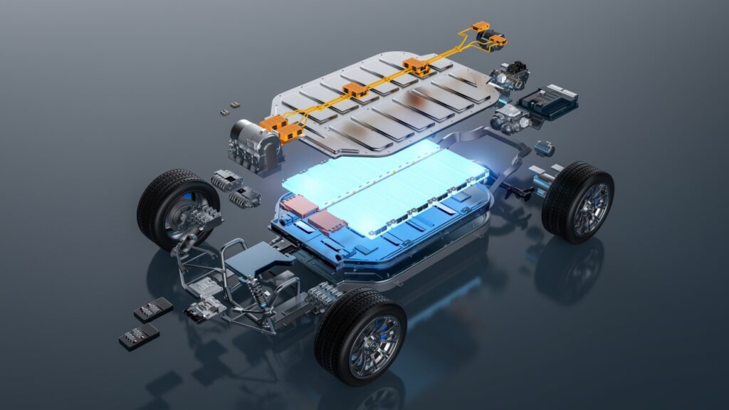
EV batteries have a structure of
Cell
↓
Thermally conductive material
↓
Cooling plate
When many cells are cooled with a single cooling plate, if only some cells have poor contact, only those cells may become hotter.
The coolant temperature is the same.
The cooling plate is also the same.
Even so, cell temperatures differ.
The cause can be
differences in the contact state of each cell.
This also affects battery life and cell-to-cell variation.
■ The Larger the Area, the Harder Contact Uniformity Becomes
With a small IC, it is relatively easy to apply uniform pressure.
But in EV batteries and large power modules, the contact area becomes large.
The larger the area, the more easily the effects of
● Warping
● Flatness
● Thickness differences
● Pressure differences
appear.
In other words, there are cases where,
for large-area components, contact uniformity across the entire surface matters more than material performance.
■ The Contact State Changes over Time
Right after assembly, it was in clean contact.
However, the contact state can change due to
● High temperatures
● Low temperatures
● Vibration
● Long-term compression
● Material degradation
The TIM pumps out.
The adhesive creeps.
The foam loses its resilience.
The component warps.
Then thermal resistance also changes.
In other words, contact thermal resistance is
not a fixed value, but may change over time.
■ Interfaces Can Also Delaminate with Thermal Cycling
When different materials are laminated, their thermal expansion coefficients also differ.
Repeated
heating
and cooling
apply stress to the interfaces.
As a result,
micro-delamination,
lifting,
and cracks
may occur.
Initial thermal performance was good.
But after thousands of thermal cycles, the temperature rises.
Such phenomena are also possible.
In other words,
the contact state cannot be judged by initial evaluation alone.
■ Contact Is Good in Prototyping but Worsens in Volume Production
In prototyping, engineers apply TIM one sheet at a time.
They remove air bubbles.
They align the position.
They check the pressure.
This makes it easy to create a good contact state.
In volume production, however,
it is applied at high speed.
It is compression-bonded by automated machines.
Material lots also change.
Equipment conditions also change.
Then
● Air bubbles
● Pressure differences
● Application misalignment
● Foreign matter
may increase.
In other words,
being able to make contact in prototyping and being able to reproduce contact in volume production are different things.
■ Failure Example: Switched to a High-Performance TIM, but the Temperature Did Not Drop
For example, the existing TIM was changed from 3 W/m·K to 8 W/m·K.
But the new material was hard.
The assembly pressure was not changed.
That is why it did not conform sufficiently in some areas, and air layers remained.
As a result,
thermal resistance inside the material decreased.
But contact thermal resistance increased.
Overall thermal performance barely changed.
This is a typical case of overlooking contact resistance.
■ Failure Example: The Heat Sink Was Enlarged, but the Effect Was Small
Because a component temperature was high, it was changed to a larger heat sink.
The heat dissipation performance of the heat sink itself improved greatly.
But the TIM between the heat-generating component and the heat sink was lifting.
In this case,
even if only the capacity on the heat sink side is raised, heat does not reach it.
In other words,
even if the exit for heat is made larger, it is meaningless if the entrance is clogged.
■ Failure Example: The Cooling Plate Temperature Is Low, but the Component Is Hot
In a liquid cooling system,
the coolant temperature is normal.
The cooling plate is also cold.
But only the semiconductor temperature is high.
In this case,
it is not necessarily that
“liquid cooling capacity is insufficient.”
Rather, it is necessary to check
the interface between the semiconductor and the cold plate,
the TIM,
flatness,
and pressure.
When the cooling plate is cold but the component is hot,
it is possible that heat is not reaching the cooling plate.
■ The Researcher's Perspective: Thermal Resistances Add Up in Series
It is easy to understand if the heat path is thought of like resistances in an electric circuit.
Heat-generating body.
Interface.
TIM.
Interface.
Cooling component.
Each has thermal resistance.
That is why, even if one place is made very high-performance, overall performance is hard to improve if another resistance is large.
What matters is
finding where the greatest thermal resistance exists.
■ The Shop-Floor Perspective: Look at the Marks Left by Peeled TIM
When a heat problem occurs, one effective check is to look at the condition of the used TIM.
For example, look at
● Compression marks
● Contact marks
● Air bubbles
● Non-contact areas
● Squeeze-out
● Foreign matter marks
Is the entire surface in uniform contact?
Is only one part not compressed?
From such information, the state of the thermal interface can sometimes be inferred.
This is information that cannot be found just by looking at material catalogs.
■ Quantifying the Contact State Is Also Important
In volume production,
“it seems to be applied neatly”
cannot be controlled.
For example,
● TIM thickness
● Thickness after compression
● Application position
● Air bubble area
● Compression bonding pressure
are controlled.
Image inspection and measurement are used as needed.
In other words,
to stabilize thermal performance, the contact state must be converted into process conditions.
■ OTIS's Perspective: Contact Thermal Resistance Is an Area Where a Processing Company Can Deliver Value
OTIS is not a company that develops TIM materials themselves.
However, the contact state changes depending on
what shape the TIM is made into,
at what thickness it is used,
where adhesive is placed,
in what position it is applied,
and how it is supplied.
In other words, contact thermal resistance is
a problem at the boundary between material performance and processing quality.
This is where there is great significance in a processing company being involved.
■ Air Bubbles Can Also Be Released Through Shape
When a large-area sheet is applied over the entire surface, air bubbles tend to remain in the center in some cases.
Depending on the application, there is the idea of making it easier to release air during lamination by
● Providing openings
● Adding slits
● Providing air escape paths
In other words, there are cases where
the shape of the thermal management material itself becomes a means of improving contact quality.
■ Partial Adhesion Can Also Improve the Contact State
Full-surface adhesion can make it easy to trap air during application.
So, depending on the application,
partial adhesion,
low-tack adhesion,
or temporary fixing
may be used, with the final contact created in the compression bonding process.
Here,
material selection,
processing shape,
and the application process
must be considered together.
■ Positioning Shapes Are Also Important
The TIM shifts 0.5 mm from the heat source.
Then it may not cover part of the heat-generating surface.
Especially in small semiconductors, 0.5 mm is significant.
So application position is stabilized using
● Asymmetric shapes
● Positioning holes
● Tabs
● Carriers
In other words,
positional accuracy also governs contact thermal resistance.
■ With Reel Supply, Also Consider Contact Quality
When components are supplied on reels,
automated machines
peel,
pick up,
transport,
apply,
and compression-bond them.
If the component deforms in any of these steps, it also affects the final contact state.
For example,
it warps during pick-up.
It stretches during peeling.
It traps air from one side during application.
To prevent such problems, it is necessary to design including even the supply format of the component.
■ What OTIS Can Do
At OTIS, through
● High-precision die-cutting of TIM
● Thin-film processing
● Microfabrication
● Opening processing
● Slit processing
● Partial adhesion
● High-precision lamination
● Lamination of dissimilar materials
● Half-cutting
● Carrier design
● Reel-to-reel processing
● Supply formats for automated application
● Image inspection
we can contribute to processing so that thermal management components are incorporated at the targeted position, thickness and contact state.
OTIS is not a company that analyzes contact thermal resistance itself.
However,
creating component shapes and volume production processes that are less likely to worsen contact thermal resistance
is an area where a processing company can contribute.
■ Outside OTIS's Expertise
OTIS is not a company that specializes in
● Development of TIM materials themselves
● Fundamental property research on contact thermal resistance
● Overall semiconductor package design
● Overall cooling equipment design
● Dedicated CFD analysis
As needed, we work with material manufacturers, customers’ design departments, analysis companies and equipment manufacturers.
Within this, OTIS can play the role of
turning materials into components that can actually make correct contact.
■ Summary: Heat Flows Not Through "High-Performance Materials" but Through "Places in Contact"
Choosing materials with high thermal conductivity.
Using large heat sinks.
Introducing liquid cooling.
Adopting vapor chambers.
All of these are effective thermal management measures.
However, if the interfaces in between are not correctly in contact, their original performance will not be achieved.
Air bubbles.
Warping.
Foreign matter.
Thickness differences.
Insufficient pressure.
Misalignment.
Such small differences stop the flow of heat.
That is why, in thermal management, what matters is not only what to use, but how to make it touch.
At the point a high-performance material is chosen, thermal management is not yet complete.
Actually applying it.
Compressing it.
Fixing it.
Mass-producing it.
Only by continuing to create the same contact state through all of these does material performance become product performance.
What matters most in the end in thermal management is often not large cooling equipment.
It is an interface of just a few tens of μm to 0.1 mm.
Column Supervisor: Koji Kakumoto (President, OTIS Co., Ltd.)
After studying abroad and working in planning and development at a trading company, he joined OTIS Co., Ltd. in 2011. While primarily working in the Corporate Planning Department, he has also served concurrently in manufacturing and technical divisions, and since 2018 has served as President, working to drive business growth and strengthen the organization.
This article is a general technical explanation intended for educational purposes and does not refer to any specific company, product, or technology.