【1】What Is Electrical Characterization?
Electrical characterization is technology that measures voltage, current, frequency, and signal quality to confirm device functions and performance.
It covers three main areas:
・DC characteristics
・RF characteristics
・High-speed digital signal characteristics
With scaling and higher speeds, measurement difficulty is increasing year by year.
【2】DC Characterization (Direct Current Characteristics)
The most fundamental evaluation.
Main measurement items:
・IV characteristics (current–voltage)
・Leakage current
・Threshold voltage (Vth)
・On-resistance (Ron)
・Dielectric withstand voltage
Purposes of evaluation:
・Confirming transistor operation
・Confirming the soundness of insulating films
・Detecting shorts and disconnections
Equipment used:
・Parameter analyzers
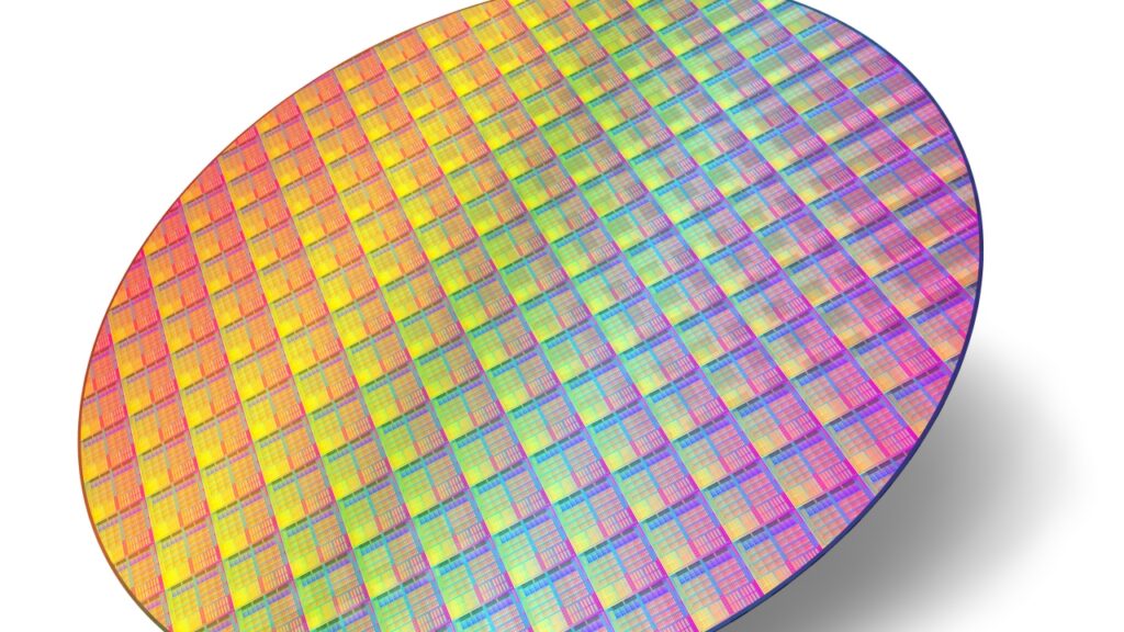
・Probers (wafer test)
DC evaluation is the first gate to confirm that the device works as designed.
【3】RF Characterization (High-Frequency Characteristics)
Essential for 5G, millimeter-wave, and AI communications.
It evaluates electrical behavior in the GHz band.
Main measurement items:
・S-parameters (S11 / S21, etc.)
・Insertion loss
・Return loss
・Gain
・Phase characteristics
Evaluation targets:
・RF chips
・Antenna ICs
・Front-end modules
Equipment used:
・Network analyzers
・RF probes
Package materials and RDL structures also have a major impact on RF characteristics.
【4】High-Speed Digital Signal Evaluation
The core area in the era of AI, GPUs, and HBM.
It handles signals of tens of Gbps or more.
Main measurement items:
・Eye patterns
・Jitter
・BER (Bit Error Rate)
・Rise / fall times
・Crosstalk
Evaluation targets:
・CPUs / GPUs
・HBM interfaces
・SerDes circuits
Equipment used:
・High-speed oscilloscopes
・BERT (Bit Error Rate Tester)
The higher the speed, the more wiring and packaging become the bottleneck.
【5】Relationship with SI / PI Evaluation
Electrical evaluation is not complete on its own.
What matters are:
・SI (Signal Integrity)
・PI (Power Integrity)
SI evaluation:
Whether signal waveforms are distorted
→ Evaluation of reflection, crosstalk, and attenuation
PI evaluation:
Whether power is being supplied stably
→ Evaluation of IR drop and power supply noise
In advanced packaging, power and signals are designed as one.
【6】How Packaging Affects Electrical Characteristics
There are many influencing factors.
Examples:
・RDL wiring length
・TSV resistance
・Bump inductance
・Substrate dielectric constant
・Low-k material properties
As a result:
・Increased delay
・Increased noise
・Increased heat generation
In other words, the package = an electrical performance component.
【7】Electrical Evaluation Challenges in the AI Chip Era
There are three characteristics:
① Ultra-high current
→ Power stability is most important
② Ultra-high-speed I/O
→ The HBM connection becomes the bottleneck
③ Ultra-high-density wiring
→ Increased crosstalk
Evaluation must be performed for the entire system, not just the chip alone.
【8】Relationship with Volume Production Testing
Electrical characterization is directly linked to volume-production yield.
Main defects:
・Shorts
・Disconnections
・Excessive leakage
・Insufficient operating frequency
Reducing test time while maintaining accuracy is the key to volume production.
【9】Summary
・Electrical characterization is at the core of functional confirmation
・It consists of three areas: DC / RF / high-speed signals
・The influence of packaging increases with higher speeds
・SI / PI evaluation is indispensable
・In AI chips, it expands into system-level evaluation
Comprehension Check
1.What is the main purpose of DC characterization?
2.What are the representative indicators used in RF evaluation?
3.Why is BER important for high-speed signals?
4.Why does advanced packaging affect electrical performance?
Column Supervisor: Koji Kakumoto (President, OTIS Co., Ltd.)
After studying abroad and working in planning and development at a trading company, he joined OTIS Co., Ltd. in 2011. While primarily working in the Corporate Planning Department, he has also served concurrently in manufacturing and technical divisions, and since 2018 has served as President, working to drive business growth and strengthen the organization.
This article is a general technical explanation intended for educational purposes and does not refer to any specific company, product, or technology.